Which Company Produced the System/360, a Family of 19 Compatible Mainframe Computers?
 | |
 IBM System/360 Model 30 key processor unit of measurement (CPU) | |
| Likewise known as | Southward/360 |
|---|---|
| Programmer | International Business organization Machines Corporation (IBM) |
| Manufacturer | IBM |
| Product family | Run into table of models |
| Blazon | Mainframe estimator |
| Release engagement | April seven, 1964 (1964-04-07) |
| Discontinued | 1978 (1978) |
| Media |
|
| Operating system |
|
| Memory | 8 KB – 9 MB (cadre memory) |
| Predecessor | 700/7000 series |
| Successor | Organization/370 |
| Related manufactures | System/360 architecture |
The IBM System/360 (South/360) is a family of mainframe computer systems that was appear past IBM on April 7, 1964, and delivered between 1965 and 1978.[one] Information technology was the showtime family of computers designed to cover both commercial and scientific applications and to encompass a complete range of applications from pocket-size to large. The design distinguished betwixt architecture and implementation, allowing IBM to release a suite of compatible designs at different prices. All but the only partially compatible Model 44 and the most expensive systems use microcode to implement the instruction set, which features 8-bit byte addressing and binary, decimal, and hexadecimal floating-betoken calculations.
The System/360 family introduced IBM's Solid Logic Technology (SLT), which packed more than transistors onto a circuit bill of fare, allowing more powerful only smaller computers to be built.[2]
The slowest System/360 model announced in 1964, the Model 30, could perform up to 34,500 instructions per second, with memory from 8 to 64 KB.[3] High-performance models came subsequently. The 1967 IBM System/360 Model 91 could execute upwards to 16.half dozen one thousand thousand instructions per second.[4] The larger 360 models could have up to 8 MB of chief retentivity,[five] though that much master retentiveness was unusual—a large installation might take every bit little every bit 256 KB of primary storage, but 512 KB, 768 KB or 1024 KB was more than common. Up to eight megabytes of slower (viii microsecond) Large Chapters Storage (LCS) was also bachelor for some models.
The IBM 360 was extremely successful in the market place, allowing customers to purchase a smaller arrangement with the noesis they would be able to move to larger ones if their needs grew, without reprogramming awarding software or replacing peripheral devices. Its design influenced computer design for years to come; many consider it one of the most successful computers in history.
The primary architect of System/360 was Gene Amdahl, and the project was managed by Fred Brooks, responsible to Chairman Thomas J. Watson Jr.[5] The commercial release was piloted by another of Watson's lieutenants, John R. Opel, who managed the launch of IBM'due south System 360 mainframe family in 1964.[six]
Application-level compatibility (with some restrictions) for Organization/360 software is maintained to the present 24-hour interval with the System z mainframe servers.
Organisation/360 history [edit]

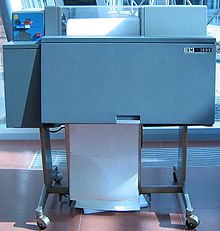
IBM Organization/360 Model 20 CPU with front panels removed, with IBM 2560 MFCM (Multi-Function Card Machine)
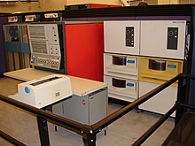
IBM System/360 Model 30 CPU (red, middle of film), record drives to its left, and deejay drives to its right, at the Reckoner History Museum

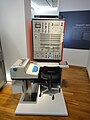
IBM System/360 Model 50 CPU, computer operator'due south panel, and peripherals at Volkswagen

A family unit of computers [edit]
Contrasting with manufacture do of the day, IBM created an entire new series of computers, from small to large, depression- to loftier-performance, all using the same instruction prepare (with ii exceptions for specific markets). This feat allowed customers to utilise a cheaper model and then upgrade to larger systems as their needs increased without the time and expense of rewriting software. Earlier the introduction of System/360, business organization and scientific applications used unlike computers with different instruction sets and operating systems. Dissimilar-sized computers also had their own instruction sets. IBM was the outset manufacturer to exploit microcode technology to implement a compatible range of computers of widely differing performance, although the largest, fastest models had hard-wired logic instead.
This flexibility greatly lowered barriers to entry. With most other vendors customers had to choose between machines they could outgrow and machines that were potentially besides powerful and thus too costly. This meant that many companies simply did not purchase computers.
Models [edit]
IBM initially announced a series of half dozen computers and forty common peripherals. IBM somewhen delivered 14 models, including rare one-off models for NASA. The to the lowest degree expensive model was the Model 20 with as niggling as 4096 bytes of core memory, viii sixteen-bit registers instead of the sixteen 32-chip registers of other Organization/360 models, and an didactics set that was a subset of that used past the residuum of the range.
The initial declaration in 1964 included Models 30, xl, fifty, threescore, 62, and lxx. The first three were low- to middle-range systems aimed at the IBM 1400 series market. All three first shipped in mid-1965. The last three, intended to supplant the 7000 series machines, never shipped and were replaced with the 65 and 75, which were beginning delivered in November 1965, and Jan 1966, respectively.
Subsequently additions to the low-terminate included models 20 (1966, mentioned above), 22 (1971), and 25 (1968). The Model 20 had several sub-models; sub-model v was at the college stop of the model. The Model 22 was a recycled Model 30 with minor limitations: a smaller maximum retentiveness configuration, and slower I/O channels, which limited it to slower and lower-capacity disk and tape devices than on the 30.
The Model 44 (1966) was a specialized model, designed for scientific computing and for real-time computing and process control, featuring some boosted instructions, and with all storage-to-storage instructions and five other complex instructions eliminated.

A succession of loftier-terminate machines included the Model 67 (1966, mentioned below, briefly predictable every bit the 64 and 66[seven]), 85 (1969), 91 (1967, predictable as the 92), 95 (1968), and 195 (1971). The 85 blueprint was intermediate between the System/360 line and the follow-on System/370 and was the basis for the 370/165. There was a System/370 version of the 195, only it did not include Dynamic Address Translation.
The implementations differed substantially, using different native data path widths, presence or absence of microcode, yet were extremely compatible. Except where specifically documented, the models were architecturally uniform. The 91, for instance, was designed for scientific computing and provided out-of-social club instruction execution (and could yield "imprecise interrupts" if a programme trap occurred while several instructions were existence read), but lacked the decimal instruction gear up used in commercial applications. New features could be added without violating architectural definitions: the 65 had a dual-processor version (M65MP) with extensions for inter-CPU signalling; the 85 introduced cache memory. Models 44, 75, 91, 95, and 195 were implemented with hardwired logic, rather than microcoded equally all other models.
The Model 67, announced in August 1965, was the first production IBM arrangement to offer dynamic address translation (virtual retention) hardware to back up time-sharing. "DAT" is at present more commonly referred to every bit an MMU. An experimental i-off unit was congenital based on a model forty. Before the 67, IBM had announced models 64 and 66, DAT versions of the threescore and 62, only they were almost immediately replaced with the 67 at the aforementioned time that the 60 and 62 were replaced with the 65. DAT hardware would reappear in the S/370 series in 1972, though information technology was initially absent from the serial. Similar its close relative, the 65, the 67 also offered dual CPUs.
IBM stopped marketing all Organization/360 models by the end of 1977.[8]
Backward compatibility [edit]
IBM's existing customers had a large investment in software that executed on 2d-generation machines. Several models offered the option of emulation of the customer'south previous figurer using a combination of special hardware,[9] special microcode and an emulation program that used the emulation instructions to simulate the target organization, so that sometime programs could run on the new machine.
| Arrangement/360 model | Emulated systems |
|---|---|
| Model xx | 1401 |
| Model 30 | 1401 1440 1460 |
| Model 40 | 1401 1440 1460 1410 7010 |
| Model l | 1401 1440 1460 1410 7010 7070, 7072 and 7074 |
| Model 65 | 7070, 7072 and 7074 7080 709 7090, 7094 7094 II 7040 and 7044 |
| Model 85 | 709 7090, 7094 7094 Two 7040 and 7044 Nether Bone command |
Customers initially had to halt the figurer and load the emulation program.[10] IBM afterward added features and modified emulator programs to allow emulation of the 1401, 1440, 1460, 1410 and 7010 under the control of an operating organisation. The Model 85 and later System/370 maintained the precedent, retaining emulation options and assuasive emulator programs to execute under operating system control alongside native programs.[11]
Successors and variants [edit]
System/360 (excepting the Model xx) was replaced with the compatible System/370 range in 1970 and Model 20 users were targeted to move to the IBM System/3. (The idea of a major breakthrough with FS engineering science was dropped in the mid-1970s for cost-effectiveness and continuity reasons.) Later compatible IBM systems include the 4300 family unit, the 308x family, the 3090, the ES/9000 and 9672 families (System/390 family), and the IBM Z serial.
Computers that were mostly identical or compatible in terms of the automobile code or architecture of the System/360 included Amdahl's 470 family (and its successors), Hitachi mainframes, the UNIVAC 9000 series,[12] Fujitsu every bit the Facom, the RCA Spectra 70 series,[NB 1] and the English Electrical System iv.[NB 2] The System 4 machines were congenital under license to RCA. RCA sold the Spectra series to what was and then UNIVAC, where they became the UNIVAC Series 70. UNIVAC also developed the UNIVAC Series 90 every bit successors to the 9000 series and Series 70.[12] The Soviet Wedlock produced a System/360 clone named the ES EVM.[xiii]
The IBM 5100 portable computer, introduced in 1975, offered an pick to execute the Arrangement/360'southward APL.SV programming linguistic communication through a hardware emulator. IBM used this approach to avoid the costs and delay of creating a 5100-specific version of APL.
Special radiation-hardened and otherwise somewhat modified System/360s, in the form of the System/4 Pi avionics reckoner, are used in several fighter and bomber jet shipping. In the complete 32-bit AP-101 version, 4 Pi machines were used as the replicated calculating nodes of the fault-tolerant Infinite Shuttle computer system (in five nodes). The U.S. Federal Aviation Administration operated the IBM 9020, a special cluster of modified System/360s for air traffic control, from 1970 until the 1990s. (Some 9020 software is apparently yet used via emulation on newer hardware.[ citation needed ])
Tabular array of System/360 models [edit]
| Model | Appear[14] | Shipped[14] | Scientific performance (kIPS)[NB 3] | Commercial performance (kIPS)[NB 4] | CPU Bandwidth (MB/sec)[fifteen] | Retentiveness bandwidth (MB/sec)[15] | Retentivity size (in (binary) KB) | Weight (lbs) | Notes |
|---|---|---|---|---|---|---|---|---|---|
| 30 | Apr 1964 | Jun 1965 | 10.2 | 29 | 1.three | 0.7 | eight-64[xvi] | 1700 (770 kg)[17] : 2030.1 | |
| twoscore | Apr 1964 | Apr 1965 | 40 | 75 | iii.2 | 0.eight | 16-256[18] | 1700-2310 (770-1050 kg) depends on retention[17] : 2040.1 | |
| l | Apr 1964 | Aug 1965 | 133 | 169 | viii.0 | 2.0 | 64-512[nineteen] | four,700-seven,135 (2,100-iii,236 kg) depends on memory[17] : 2050.two, 2050.iv | Supported IBM 2361 Large Capacity Storage (LCS). |
| 60 - 62 | Apr 1964 | never | Replaced by Model 65 | ||||||
| 70 | April 1964 | never | Replaced by Model 75 | ||||||
| xc | Apr 1964 | never | Replaced by Model 92 | ||||||
| 92 | Aug 1964 | never | Redesignated every bit IBM System/360 Model 91[14] | ||||||
| 20 | Nov 1964 | Mar 1966 | ii.0 | 2.6 | 4-32[20] | 1,200–1,400 (540–640 kg)[21] | 16-scrap, low end, limited partially incompatible instruction set | ||
| 91 | Jan 1966[xiv] : p.394 | October 1967 | one,900 | 1,800 | 133 | 164 | 1,024-four,096[22] | Available on special bid beginning Nov 1964[14] : 388 | |
| 64, 66 | Apr 1965 | never | Replaced past Model 67 | ||||||
| 65 | April 1965 | Nov 1965 | 563 | 567 | 40 | 21 | 128-1,024[23] | 4290-8830 (1950-4005 kg) depends on memory and number of processors[17] : 2065.two, 2065.4, 2065.6, 2065.viii, 2065.10 | Supported LCS |
| 75 | Apr 1965 | Jan 1966 | 940 | 670 | 41 | 43 | 256-i,024[24] | 5125-5325 (2325-2415 kg) depends on retentiveness[17] : 2075.2, 2075.iv | Supported LCS |
| 67 | Aug 1965 | May 1966 | 40 | 21 | 512-2,048[25] | 3674 (1700 kg) - Processor only[17] : 2067.six | Dynamic address translation for time sharing | ||
| 44 | Aug 1965 | Sep 1966 | 118 | 185 | 16 | 4.0 | 32-256[26] | 2900-4200 (1300-1900 kg) depends on memory[17] : 2044.2 | Specialized for scientific computing |
| 95 | special social club | Feb 1968 | three,800 est. | 3,600 est. | 133 | 711 | 5,220[27] | Performance estimated as 2× Model 91[fourteen] : p.394 | |
| 25 | Jan 1968 | Oct 1968 | 9.7 | 25 | ane.ane | two.two | 16-48[28] | 2050 (930 kg)[17] : 2025.two | |
| 85 | Jan 1968 | Dec 1969 | 3,245 | 3,418 | 100 | 67 | 512-4,096[29] | 14428 (6544 kg) - Processor only[17] : 2085.2 | 16-32 KB enshroud memory, extended-precision floating indicate. |
| 195 | Aug 1969 | Mar 1971 | 10,000 est. | 10,000 est. | 148 | 169 | ane,024-4,096[thirty] | 13450-28350 (6150-12900 kg) depends on retention[17] : 3195.ii, 3195.4 | 32 KB IC cache retention. Functioning estimated every bit three× Model 85.[14] : p.422 |
| 22 | Apr 1971 | Jun 1971 | 1.iii | 0.7 | 24-32[31] | 1500 (680 kg)[17] : 2022.1 | A re-manufactured Model 30 |
- Model summary
- Six of the twenty IBM System/360 models announced either were never shipped or were never released.
- Fourteen of the xx IBM Arrangement/360 models appear shipped.
Technical clarification [edit]
Influential features [edit]

The System/360 introduced a number of industry standards to the marketplace, such equally:
- The viii-chip byte (against financial force per unit area during evolution to reduce the byte to 4 or 6 $.25), rather than adopting the 7030 concept of accessing bytes of variable size at arbitrary bit addresses.
- Byte-addressable retentiveness (equally opposed to bit-addressable or word-addressable memory)
- 32-scrap words
- The Coach and Tag I/O channel standardized in FIPS-60[32]
- Commercial employ of microcoded CPUs
- The IBM Floating Indicate Architecture
- The EBCDIC character set[NB 5]
- 9 track magnetic tape
Architectural overview [edit]
The Organization/360 series has a computer organization architecture specification.[33] [34] [35] This specification makes no assumptions on the implementation itself, just rather describes the interfaces and expected behavior of an implementation. The architecture describes mandatory interfaces that must be bachelor on all implementations, and optional interfaces. Some aspects of this architecture are:
- Large endian byte ordering
- A processor with
- sixteen 32-flake general purpose registers (R0-R15)
- A 64-bit programme condition word (PSW), which describes (amongst other things)
- Interrupt masks
- Privilege states
- A condition lawmaking
- A 24-bit instruction address
- An suspension mechanism, maskable and unmaskable interruption classes and subclasses
- An instruction set. Each instruction is wholly described and also defines the conditions under which an exception is recognized in the course of programme interruption.
- A memory (chosen storage) subsystem with
- 8 $.25 per byte
- A special processor communication surface area starting at address 0
- 24-chip addressing
- Transmission command operations that permit
- A bootstrap process (a process chosen Initial Program Load or IPL)
- Operator-initiated interrupts
- Resetting the system
- Basic debugging facilities
- Manual brandish and modifications of the organisation'south country (retentiveness and processor)
- An Input/Output mechanism - which does not describe the devices themselves
Some of the optional features are:
- Binary-coded decimal instructions
- Floating signal instructions
- Timing facilities (interval timer)
- Key-controlled memory protection
All models of Arrangement/360, except for the Model 20 and Model 44, implemented that specification.
Binary arithmetic and logical operations are performed as annals-to-register and as retentivity-to-register/register-to-memory every bit a standard feature. If the Commercial Instruction Set up choice was installed, packed decimal arithmetic could be performed every bit memory-to-memory with some memory-to-annals operations. The Scientific Instruction Set feature, if installed, provided access to four floating point registers that could be programmed for either 32-bit or 64-bit floating betoken operations. The Models 85 and 195 could also operate on 128-bit extended-precision floating indicate numbers stored in pairs of floating point registers, and software provided emulation in other models. The System/360 used an viii-bit byte, 32-bit word, 64-bit double-word, and iv-bit nibble. Machine instructions had operators with operands, which could contain register numbers or retention addresses. This complex combination of instruction options resulted in a diverseness of teaching lengths and formats.
Memory addressing was accomplished using a base-plus-displacement scheme, with registers one through F (15). A displacement was encoded in 12 $.25, thus assuasive a 4096-byte displacement (0-4095), as the offset from the accost put in a base register.
Register 0 could not be used equally a base register nor as an index annals (nor every bit a co-operative address annals), as "0" was reserved to indicate an accost in the first 4 KB of memory, that is, if annals 0 was specified every bit described, the value 0x00000000 was implicitly input to the effective accost calculation in place of whatsoever value might be independent within annals 0 (or if specified as a branch accost annals, then no branch was taken, and the content of register 0 was ignored, but any side upshot of the instruction was performed).
This specific beliefs permitted initial execution of an interrupt routines, since base registers would not necessarily exist set to 0 during the first few instruction cycles of an interrupt routine. Information technology isn't needed for IPL ("Initial Program Load" or kick), equally one can ever clear a register without the need to salvage information technology.
With the exception of the Model 67,[25] all addresses were real retention addresses. Virtual memory was not bachelor in most IBM mainframes until the Organization/370 series. The Model 67 introduced a virtual memory architecture, which MTS, CP-67, and TSS/360 used—but not IBM's mainline System/360 operating systems.
The Organisation/360 machine-code instructions are 2 bytes long (no memory operands), 4 bytes long (1 operand), or 6 bytes long (two operands). Instructions are e'er situated on 2-byte boundaries.
Operations like MVC (Move-Characters) (Hex: D2) can just move at almost 256 bytes of information. Moving more than 256 bytes of data required multiple MVC operations. (The Arrangement/370 series introduced a family of more powerful instructions such equally the MVCL "Motility-Characters-Long" instruction, which supports moving upwardly to 16 MB as a single block.)
An operand is ii bytes long, typically representing an accost equally a four-scrap crumb denoting a base register and a 12-bit displacement relative to the contents of that register, in the range 000–FFF (shown hither as hexadecimal numbers). The address corresponding to that operand is the contents of the specified general-purpose register plus the displacement. For case, an MVC teaching that moves 256 bytes (with length code 255 in hexadecimal as FF) from base of operations register vii, plus displacement 000, to base of operations register 8, plus displacement 001, would be coded as the 6-byte instruction "D2FF 8001 7000" (operator/length/address1/address2).
The Arrangement/360 was designed to separate the arrangement state from the problem state. This provided a basic level of security and recoverability from programming errors. Problem (user) programs could not modify data or plan storage associated with the organisation state. Addressing, information, or operation exception errors fabricated the machine enter the system state through a controlled routine and so the operating system could try to right or terminate the program in fault. Similarly, information technology could recover sure processor hardware errors through the machine check routines.
Channels [edit]
Peripherals interfaced to the system via channels. A aqueduct is a specialized processor with the educational activity gear up optimized for transferring data between a peripheral and main memory. In modern terms, this could be compared to straight retentivity access (DMA). The South/360 connects channels to control units with bus and tag cables; IBM eventually replaced these with (Enterprise Systems Connection (ESCON) and Fibre Connectedness (FICON) channels.
Byte-multiplexor and selector channels [edit]
There were initially two types of channels; byte-multiplexer channels (known at the time only equally "multiplexor channels"), for connecting "slow speed" devices such every bit menu readers and punches, line printers, and communications controllers, and selector channels for connecting high speed devices, such as disk drives, record drives, data cells and drums. Every Organisation/360 (except for the Model 20, which was not a standard 360) has a byte-multiplexer aqueduct and 1 or more selector channels, though the model 25 has just one channel, which can be either a byte-multiplexor or selector channel. The smaller models (up to the model 50) accept integrated channels, while for the larger models (model 65 and above) the channels are large separate units in split up cabinets: the IBM 2870 is the byte-multiplexor channel with upward to four selector sub-channels, and the IBM 2860 is upwardly to three selector channels.
The byte-multiplexer aqueduct is able to handle I/O to/from several devices simultaneously at the device's highest rated speeds, hence the name, as information technology multiplexed I/O from those devices onto a single data path to main retentivity. Devices connected to a byte-multiplexer channel are configured to operate in one-byte, two-byte, iv-byte, or "burst" mode. The larger "blocks" of data are used to handle progressively faster devices. For instance, a 2501 card reader operating at 600 cards per infinitesimal would be in i-byte mode, while a 1403-N1 printer would be in burst manner. Also, the byte-multiplexer channels on larger models accept an optional selector subchannel section that would adjust tape drives. The byte-multiplexor'south aqueduct address was typically "0" and the selector subchannel addresses were from "C0" to "FF." Thus, tape drives on System/360 were commonly addressed at 0C0-0C7. Other common byte-multiplexer addresses are: 00A: 2501 Menu Reader, 00C/00D: 2540 Reader/Punch, 00E/00F: 1403-N1 Printers, 010-013: 3211 Printers, 020-0BF: 2701/2703 Telecommunication Units. These addresses are withal commonly used in z/VM virtual machines.
System/360 models 40 and 50 have an integrated 1052-7 console that is ordinarily addressed as 01F, even so, this was not connected to the byte-multiplexer channel, but rather, had a direct internal connection to the mainframe. The model 30 attached a different model of 1052 through a 1051 control unit. The models lx through 75 also use the 1052-vii.

Cablevision used as Double-decker or Tag cable for IBM Arrangement/360

Selector channels enabled I/O to loftier speed devices. These storage devices were attached to a command unit then to the aqueduct. The control unit permit clusters of devices exist attached to the channels. On higher speed models, multiple selector channels, which could operate simultaneously or in parallel, improved overall operation.
Control units are connected to the channels with "bus and tag" cable pairs. The bus cables carried the address and data information and the tag cables identified what data was on the jitney. The general configuration of a channel is to connect the devices in a concatenation, like this: Mainframe—Control Unit X—Command Unit Y—Command Unit of measurement Z. Each command unit is assigned a "capture range" of addresses that it services. For instance, control unit X might capture addresses 40-4F, control unit Y: C0-DF, and control unit Z: 80-9F. Capture ranges had to be a multiple of 8, 16, 32, 64, or 128 devices and exist aligned on appropriate boundaries. Each control unit in plough has one or more devices fastened to it. For example, y'all could have control unit Y with half dozen disks, that would be addressed as C0-C5.
In that location are three general types of bus-and-tag cables produced past IBM. The showtime is the standard gray motorcoach-and-tag cable, followed past the blue bus-and-tag cable, and finally the tan autobus-and-tag cablevision. Generally, newer cable revisions are capable of higher speeds or longer distances, and some peripherals specified minimum cable revisions both upstream and downstream.
The cable ordering of the command units on the channel is also meaning. Each control unit is "strapped" as Loftier or Depression priority. When a device selection was sent out on a mainframe's channel, the pick was sent from Ten->Y->Z->Y->10. If the control unit was "high" then the choice was checked in the outbound management, if "low" then the inbound direction. Thus, control unit X was either 1st or 5th, Y was either 2d or 4th, and Z was 3rd in line. It is also possible to accept multiple channels attached to a command unit from the same or multiple mainframes, thus providing a rich high-performance, multiple-access, and fill-in capability.
Typically the full cablevision length of a channel is limited to 200 anxiety, less beingness preferred. Each control unit accounts for about 10 "feet" of the 200-pes limit.
Block multiplexer channel [edit]
IBM showtime introduced a new type of I/O channel on the Model 85 and Model 195, the 2880 cake multiplexer channel, and so made them standard on the Arrangement/370. This channel allowed a device to suspend a aqueduct programme, pending the completion of an I/O operation and thus to costless the channel for use by another device. A block multiplexer channel can support either standard ane.five MB/second connections or, with the ii-byte interface feature, 3 MB/second; the latter use i tag cablevision and two double-decker cables. On the S/370 at that place is an option for a 3.0 MB/southward data streaming[36] channel with one charabanc cable and i tag cable.
The initial utilise for this was the 2305 fixed-head disk, which has viii "exposures" (alias addresses) and rotational position sensing (RPS).
Cake multiplexer channels can operate as a selector channel to allow compatible attachment of legacy subsystems.[37]
Basic hardware components [edit]


Many SLT cards plugged into an SLT board.
Existence uncertain of the reliability and availability of the then new monolithic integrated circuits, IBM chose instead to design and manufacture its own custom hybrid integrated circuits. These were built on 11 mm square ceramic substrates. Resistors were silk screened on and discrete glass encapsulated transistors and diodes were added. The substrate was then covered with a metal lid or encapsulated in plastic to create a "Solid Logic Engineering" (SLT) module.
A number of these SLT modules were then flip chip mounted onto a pocket-size multi-layer printed circuit "SLT card". Each card had one or two sockets on i edge that plugged onto pins on one of the estimator's "SLT boards". This was the contrary of how most other company's cards were mounted, where the cards had pins or printed contact areas and plugged into sockets on the figurer'south boards.
Up to xx SLT boards could be assembled side-by-side (vertically and horizontally) to course a "logic gate". Several gates mounted together constituted a box-shaped "logic frame". The outer gates were generally hinged along one vertical edge and then they could be swung open to provide access to the fixed inner gates. The larger machines could have more than one frame bolted together to produce the last unit of measurement, such as a multi-frame Central Processing Unit (CPU).
Operating system software [edit]
The smaller Organization/360 models used the Basic Operating System/360 (BOS/360), Tape Operating Organization (TOS/360), or Disk Operating System/360 (DOS/360, which evolved into DOS/VS, DOS/VSE, VSE/AF, VSE/SP, VSE/ESA, and then z/VSE).
The larger models used Operating Arrangement/360 (Os/360). IBM developed several levels of OS/360, with increasingly powerful features: Main Control Program (PCP), Multiprogramming with a Fixed number of Tasks (MFT), and Multiprogramming with a Variable number of Tasks (MVT). MVT took a long time to develop into a usable system, and the less ambitious MFT was widely used. PCP was used on intermediate machines too small to run MFT well, and on larger machines before MFT was available; the last releases of Os/360 included only MFT and MVT. For the Arrangement/370 and afterwards machines, MFT evolved into OS/VS1, while MVT evolved into OS/VS2 (SVS) (Single Virtual Storage), then various versions of MVS (Multiple Virtual Storage) culminating in the current z/OS.
When information technology announced the Model 67 in August 1965, IBM also announced TSS/360 (Time-Sharing System) for delivery at the same time equally the 67. TSS/360, a response to Multics, was an ambitious project that included many advanced features. Information technology had functioning bug, was delayed, canceled, reinstated, and finally canceled[NB 6] over again in 1971. Customers migrated to CP-67, MTS (Michigan Terminal System), TSO (Fourth dimension Sharing Selection for OS/360), or one of several other fourth dimension-sharing systems.
CP-67, the original virtual machine organization, was besides known as CP/CMS. CP/67 was adult outside the IBM mainstream at IBM'southward Cambridge Scientific Eye, in cooperation with MIT researchers. CP/CMS eventually won wide credence, and led to the evolution of VM/370 (Virtual Machine) which had a primary interactive "sub" operating system known every bit VM/CMS (Conversational Monitoring System). This evolved into today's z/VM.
The Model 20 offered a simplified and rarely used record-based system called TPS (Tape Processing System), and DPS (Deejay Processing System) that provided support for the 2311 disk drive. TPS could run on a machine with viii KB of memory; DPS required 12 KB, which was pretty hefty for a Model 20. Many customers ran quite happily with iv KB and CPS (Card Processing System). With TPS and DPS, the carte reader was used to read the Job Control Language cards that defined the stack of jobs to run and to read in transaction data such as client payments. The operating arrangement was held on record or disk, and results could too exist stored on the tapes or hard drives. Stacked job processing became an heady possibility for the small but adventurous computer user.
A little-known and little-used suite of 80-column punched-card utility programs known equally Basic Programming Back up (BPS) (jocularly: Barely Programming Support), a precursor of TOS, was bachelor for smaller systems.
Component names [edit]
IBM created a new naming system for the new components created for System/360, although well-known old names, like IBM 1403 and IBM 1052, were retained. In this new naming system, components were given four-digit numbers starting with ii. The 2nd digit described the type of component, as follows:
| 20xx: | Arithmetic processors, for example the IBM 2030, which was the CPU for the IBM System/360 Model 30. |
| 21xx: | Ability supplies and other equipment intimately associated with processors, for example the IBM 2167 Configuration Unit. |
| 22xx: | Visual output devices, for example the IBM 2250 and IBM 2260 CRT displays, and the IBM 2203 line printer for the System/360 model xx. |
| 23xx: | Direct-access storage devices, for example the IBM 2311 and IBM 2314 deejay drives, the IBM 2321 Data Cell; Main storage such equally the IBM 2361 Large Capacity Storage (Core Storage, Large Cadre Storage or LCS) and the IBM 2365 Processor Storage. |
| 24xx: | Magnetic tape drives, for example the IBM 2401, IBM 2405 and IBM 2415. |
| 25xx: | Punched carte du jour handling equipment, for example the IBM 2501 (card reader), IBM 2520 (carte du jour punch); IBM 2540 (reader/punch) and IBM 2560 (Multi-Office Bill of fare Machine or MFCM). |
| 26xx: | Paper record handling equipment, for instance the IBM 2671 paper tape reader. |
| 27xx: | Communications equipment, for example the IBM 2701, IBM 2705, IBM 2741 interactive terminal and the IBM 2780 batch final. |
| 28xx: | Channels and controllers, for example the IBM 2821 Control Unit, IBM 2841 and IBM 2844. |
| 29xx: | Miscellaneous devices, for example the IBM 2914 Data Aqueduct Switch and the IBM 2944 Data Channel Repeater. |
Peripherals [edit]
IBM developed a new family of peripheral equipment for Organisation/360, carrying over a few from its older 1400 series. Interfaces were standardized, allowing greater flexibility to mix and match processors, controllers and peripherals than in the before product lines.
In addition, Arrangement/360 computers could apply certain peripherals that were originally developed for earlier computers. These before peripherals used a unlike numbering system, such equally the IBM 1403 chain printer. The 1403, an extremely reliable device that had already earned a reputation as a workhorse, was sold as the 1403-N1 when adapted for the System/360.
Too available were optical character recognition (OCR) readers IBM 1287 and IBM 1288 which could read Alpha Numeric (A/Due north) and Numeric Hand Printed (NHP/NHW) Characters from Cashier's rolls of tape to full legal size pages. At the time this was done with very large optical/logic readers. Software was likewise slow and expensive at that fourth dimension.
Models 65 and below sold with an IBM 1052-7 as the console typewriter. The 360/85 with feature 5450 uses a display console that was not uniform with annihilation else in the line;[38] [39] the later 3066 console for the 370/165 and 370/168 employ the aforementioned basic brandish design as the 360/85. The IBM System/360 models 91 and 195 use a graphical display similar to the IBM 2250 every bit their master panel.
Additional operator consoles were also available. Certain high-terminate machines could optionally exist purchased with a 2250 graphical display, costing upwards of The states $100,000; smaller machines could use the less expensive 2260 display or subsequently the 3270.
Directly access storage devices (DASD) [edit]

The first disk drives for Organisation/360 were IBM 2302s[40] : 60–65 and IBM 2311s.[40] : 54–58 The first pulsate for System/360 was the IBM 7320.[41] [42] : 41
The 156 KB/2d 2302 was based on the before 1302 and was available as a model 3 with ii 112.79 MB modules[40] : threescore or equally a model 4 with four such modules.[xl] : 60
The 2311, with a removable 1316 disk pack, was based on the IBM 1311 and had a theoretical capacity of seven.2 MB, although actual capacity varied with record design.[42] : 31 (When used with a 360/xx, the 1316 pack was formatted into fixed-length 270 byte sectors, giving a maximum capacity of 5.4MB.)
In 1966, the first 2314s shipped. This device had upwards to eight usable deejay drives with an integral control unit; there were nine drives, merely one was reserved as a spare. Each drive used a removable 2316 disk pack with a chapters of nearly 28 MB. The deejay packs for the 2311 and 2314 were physically large by today'south standards — e.1000., the 1316 disk pack was about 14 in (36 cm) in diameter and had vi platters stacked on a fundamental spindle. The top and bottom exterior platters did not store information. Information were recorded on the inner sides of the top and bottom platters and both sides of the inner platters, providing 10 recording surfaces. The 10 read/write heads moved together beyond the surfaces of the platters, which were formatted with 203 concentric tracks. To reduce the amount of head movement (seeking), information was written in a virtual cylinder from inside top platter down to inside lesser platter. These disks were non ordinarily formatted with fixed-sized sectors as are today'southward hard drives (though this was done with CP/CMS). Rather, most System/360 I/O software could customize the length of the data tape (variable-length records), as was the example with magnetic tapes.

IBM 2314 deejay drives and IBM 2540 card reader/punch at the University of Michigan
Some of the most powerful early System/360s used high-speed caput-per-rail drum storage devices. The 3,500 RPM 2301,[43] which replaced the 7320, was part of the original System/360 proclamation, with a chapters of 4 MB. The 303.8 KB/second IBM 2303[forty] : 74–76 was appear on January 31, 1966, with a capacity of 3.913 MB. These were the but drums appear for System/360 and System/370, and their niche was later filled by fixed-head disks.
The six,000 RPM 2305 appeared in 1970, with capacities of 5 MB (2305-1) or 11 MB (2305-2) per module.[44] [45] Although these devices did not have large chapters, their speed and transfer rates fabricated them attractive for high-performance needs. A typical employ was overlay linkage (e.k. for OS and application subroutines) for program sections written to alternating in the same retention regions. Fixed head disks and drums were particularly effective as paging devices on the early virtual retention systems. The 2305, although often called a "pulsate" was actually a caput-per-rail disk device, with 12 recording surfaces and a data transfer rate up to 3 MB per second.
Rarely seen was the IBM 2321 Data Cell,[46] a mechanically complex device that independent multiple magnetic strips to concord data; strips could be randomly accessed, placed upon a cylinder-shaped drum for read/write operations; and then returned to an internal storage cartridge. The IBM Information Jail cell [noodle picker] was among several IBM trademarked "speedy" mass online direct-access storage peripherals (reincarnated in recent years equally "virtual record" and automated tape librarian peripherals). The 2321 file had a chapters of 400 MB, at the time when the 2311 disk drive just had 7.ii MB. The IBM Data Cell was proposed to make full cost/capacity/speed gap betwixt magnetic tapes—which had loftier chapters with relatively depression cost per stored byte—and disks, which had higher expense per byte. Some installations besides found the electromechanical operation less dependable and opted for less mechanical forms of straight-admission storage.
The Model 44 was unique in offering an integrated unmarried-disk drive as a standard characteristic. This drive used the 2315 "ramkit" cartridge and provided 1,171,200 bytes of storage.[26] : 11
Tape drives [edit]

The 2400 record drives consisted of a combined drive and command unit, plus individual one/2" tape drives attached. With Organization/360, IBM switched from IBM vii track to 9 track tape format. 2400 drives could be purchased that read and wrote 7-track tapes for compatibility with the older IBM 729 tape drives. In 1967, a slower and cheaper pair of tape drives with integrated control unit was introduced: the 2415. In 1968, the IBM 2420 record organization was released, offering much higher data rates, self-threading tape operation and 1600bpi packing density. It remained in the product line until 1979.
Unit tape devices [edit]
- Punched card devices included the 2501 card reader and the 2540 card reader punch. Virtually every System/360 had a 2540. The 2560 MFCM ("Multi-Role Card Machine") reader/sorter/punch, listed above, was for the Model twenty only. It was notorious for reliability issues (earning humorous acronyms frequently involving "...Card Muncher" or "Mal-Office Card Car").
- Line printers were the IBM 1403 and the slower IBM 1443.
- A paper record reader, the IBM 2671, was introduced in 1964. It had a rated speed of 1,000 cps. At that place were also a paper record reader and paper tape punch from an before era, available just as RPQs (Asking Price Quotation). The 1054 (reader) and 1055 (dial), which were carried forward (like the 1052 console typewriter) from the IBM 1050 Teleprocessing System. All these devices operated at a maximum of fifteen.5 characters per second. The paper tape punch from the IBM 1080 Arrangement was also available by RPQ, but at a prohibitively expensive price.
- Optical grapheme recognition (OCR) devices 1287 and afterwards the 1288 were available on the 360's. The 1287 could read handwritten numerals, some OCR fonts, and cash annals OCR paper tape reels. The 1288 'page reader' could handle up to legal size OCR font typewritten pages, as well as handwritten numerals. Both of these OCR devices employed a 'flying spot' scanning principle, with the raster scan provided by a large CRT, and the reflected lite density changes were picked upwards past a high gain photomultiplier tube.
- Magnetic ink graphic symbol recognition (MICR) was provided by the IBM 1412 and 1419 cheque sorters, with magnetic ink printing (for check books) on 1445 printers (a modified 1443 that used an MICR ribbon). 1412/1419 and 1445 were mainly used by banking institutions.
Remaining machines [edit]
Despite having been sold or leased in very large numbers for a mainframe system of its era only a few of Organisation/360 computers remain mainly as non-operating property of museums or collectors. Examples of existing systems include:
- The Calculator History Museum in Mountain View, California has a non-working Model 30 on display, as do the Museum of Transport and Technology (Motat) in Auckland, New Zealand and the Vienna University of Technology in Austria.
- The University of Western Commonwealth of australia Calculator Club has a consummate Model forty in storage.[47]
- The KCG Computer Museum of Kyoto Computer Gakuin, Japan's first computer schoolhouse in town, has an IBM Organisation/360 Model forty on brandish.[48]
- Two IBM System/360 Model xx processors along with numerous peripherals (forming at least one complete system) located in Nuremberg, Frg were purchased on eBay in April/May 2019 for €3710 by ii UK enthusiasts who, over the form of some months, moved the machine to Creslow Park in Buckinghamshire, United kingdom of great britain and northern ireland. The system was in a small, abandoned building left untouched for decades, and apparently had been used in that edifice since all peripherals were still fully wired and interconnected. The systems are now in a dedicated automobile room, and are undergoing restoration in preparation for public display in the future.[49]
A running listing of remaining System/360s that are more than only 'front end panels' tin can be institute at World Inventory of remaining System/360 CPUs.
Gallery [edit]
This gallery shows the operator'due south panel, with register value lamps, toggle switches (center of pictures), and "emergency pull" switch (upper right of pictures) of the various models.
-

Model xxx
-

Model forty
-

Model 44
-
Model l
-

Model 65
-

Model 67
-
Model 85
-

Model 91
Run into also [edit]
- History of IBM
- Listing of IBM products
- IBM System/4 Pi
- Gerrit Blaauw
- Bob O. Evans
Notes [edit]
- ^ The RCA Spectra 70 had radically unlike architecture for interrupts and I/O. There were compatibility packages to permit operating systems for System/360 to run on a Spectra/70 and vice versa.
- ^ Intended for real-fourth dimension processing, the English Electric System 4 employed four processor states, each with its ain set up of general purpose registers. Instructions bachelor in the user state were identical to the Arrangement 360. The other states were entered according to the form or severity of interrupt. The 4th (the highest) state was entered when power failure was imminent, and enabled the processor to shut itself down in an orderly mode.
- ^ Performance calculated (not measured) based on a mix of instructions typical of scientific applications ("Gibson Mix") with the results in kilo Instructions Per Second (kIPS) per Longbottom, Roy. "Computer Speeds From Instruction Mixes - pre-1960 to 1971". Retrieved October 12, 2014. except for M95 and M195. The latter based upon estimates of performance relative to M65 from Pugh.
- ^ Using commercial instruction mix ("ADP Mix")
- ^ In System/360 architecture bit 12 of the program status word (PSW) controlled selection betwixt the EBCDIC or a then proposed ASCII-8 way signed decimal data. The proposed ASCII-8 ANSI standard was in the approval process when System/360 was appear but information technology was subsequently rejected and no ASCII peripheral devices were made available. This capability was not included in Organisation/370; bit 12 of the PSW was redefined to switch between Organization/360 (BC way) and System/370 (EC mode) PSW format.
- ^ However, it could still exist ordered, and a TSS/370 PRPQ was bachelor on the Southward/370 and went through multiple releases.
References [edit]
- ^ "IBM System/360 Dates and Characteristics". IBM. 2003-01-23.
- ^ "Why won't you Dice? IBM'south S/360 and its legacy at 50". The Annals.
- ^ "System 360/30 announcement". IBM. 2003-01-23.
- ^ "Organisation 360 Model 91". IBM. 2003-01-23.
- ^ a b "Organisation/360 Announcement" (printing release), IBM Information Processing Partitioning, April 7, 1964, webpage: IBM-PR360: states bike fourth dimension from "...millionth-of-a-2nd to but 200 billionths-of-a-second," and "...retention chapters ranges from 8,000 characters of information to more 8,000,000."
- ^ "IBM - Former CEO John Opel - An Appreciation". IBM.
- ^ DIGITAL COMPUTER NEWSLETTER, Office of Naval Research, Mathematical Sciences Division, July 1965--pages 5-6: IBM Arrangement/360 time-sharing computers
- ^ Elliott, Jim (2010). "IBM Mainframes – 45+ Years of Evolution" (PDF). IBM Canada Ltd. p. 17. shows the announcement, ship and withdrawal dates for all Southward/360 models other than the transient models 64 and 66
- ^ Arrangement/370 Model 165 Theory of Performance (Book 8) 709/7090/7094/7094-II Compatibility Feature. 2d Edition. IBM. February 1971. SY77-6835-0.
- ^ Arrangement/360, Model xxx 1401 Compatibility Characteristic (PDF). IBM. April 1964. A24-3255-one.
Mode condition (Arrangement/360, Model thirty, manner or 1401 compatibility mode) is set during the read-in of the compatibility initialization deck.
- ^ Emulating the IBM 7094 on the IBM Models 85 and 165 using OS/360 Program Number for Thou/85: 360C-Eu-734 Program Number for Grand/165: 360C-European union-740 Os Release 20. 3rd Edition. IBM. Nov 1971. GC27-6951-2.
- ^ a b Gray, George T.; Smith, Ronald Q. (2001). "Sperry Rand's Third-Generation Computers 1964-1980". IEEE Register of the History of Computing. IEEE Figurer Club. 23 (1): 3–sixteen. doi:x.1109/85.910845.
- ^ "Account of Soviet cloning of the IBM-360, from Pioneers of Soviet Computing by Boris Malinovsky". Archived from the original on 2012-08-29. Retrieved 2012-09-30 .
- ^ a b c d eastward f grand Pugh, Emerson Due west.; Johnson, Lyle R.; Palmer, John H. (1991). IBM's 360 and Early 370 Systems . MIT. ISBN0-262-16123-0. References are to Appendix A unless page otherwise noted.
- ^ a b Padegs, A. (September 1981). "System/360 and Beyond". IBM Journal of Research and Development. IBM. 25 (5): 377–390. doi:10.1147/rd.255.0377.
- ^ IBM System/360 Model 30 Functional Characteristics (PDF). IBM. August 1971.
- ^ a b c d e f thou h i j thou IBM Organization/360 Installation Transmission - Physical Planning (PDF). IBM. February 1974. GC22-6820-12.
- ^ IBM Organization/360 Model forty Functional Characteristics (PDF). IBM. A22-6881-two.
- ^ IBM System/360 Model l Functional Characteristics (PDF). IBM. 1967. A22-6898-1.
- ^ IBM System/360 Model 20 Disk Programming System Control and Service Programs (PDF). IBM. March 1969. C24-9006-4.
- ^ Stuart, Sam (2014-05-23). "IBM 360/20". British Commercial Computer Digest: Pergamon Calculator Data Serial. Elsevier. pp. 3/65. ISBN9781483148588.
- ^ IBM Organisation/360 Model 91 Functional Characteristics (PDF). IBM. November 1971. GA22-6907-3.
- ^ IBM System/360 Model 65 Functional Characteristics (PDF). IBM. September 1968. A22-6884-3.
- ^ IBM Organisation/360 Model 75 Functional Characteristics (PDF). IBM. A22-6889-0.
- ^ a b IBM System/360 Model 67 Functional Characteristics (PDF). Third Edition. IBM. Feb 1972. GA27-2719-2.
- ^ a b IBM System/360 Model 44 Functional Characteristics (PDF). IBM. A22-6875-v.
- ^ "IBM System/360 Model 95". IBM.
- ^ IBM System/360 Model 25 Functional Characteristics (PDF). IBM. January 1968. A24-3510-0.
- ^ IBM System/360 Model 85 Functional Characteristics (PDF). IBM. June 1968. A22-6916-i.
- ^ IBM Organization/360 Model 195 Functional Characteristics (PDF). IBM. August 1970. GA22-6943-1.
- ^ "IBM System/360 Model 22". IBM.
- ^ NTIS (1979), I/O Channel Interface, National Technical Information Service, FIPSPUB60
- ^ IBM System/360 Principles of Functioning (PDF). First Edition. IBM. 1964. A22-6821-0.
- ^ IBM System/360 Principles of Functioning. Ninth Edition (concluding edition). Poughkeepsie, NY: IBM. Nov 1970. OCLC 1026271. A22-6821-8.
- ^ IBM Arrangement/360 I/O Interface Aqueduct to Command Unit of measurement Original Equipment Manufacturers' Information (PDF). Fifth Edition. IBM. A22-6843-3.
- ^ "Data-Streaming Feature", IBM System/360 and System/370 I/O Interface Channel to Command Unit Original Equipment Manufacturers' Data (PDF) (Tenth ed.), IBM, February 1988, pp. three-four–3-7
- ^ System/370 Principles of Operation (PDF). IBM. September 1975. p. 189. GA22-7000-4. Retrieved December 30, 2015.
- ^ IBM System/360 Operating Organisation Operator's Guide for Display Consoles (PDF). IBM Corporation. 1972. p. nine. Retrieved July thirteen, 2020.
- ^ IBM Organisation/360 Operating System MVT Supervisor (PDF). Program Logic (Eighth ed.). IBM. May 1973. GY28-6659-7.
- ^ a b c d east IBM System/360 Component Descriptions - 2841 and Associated DASD (PDF). Eighth Edition. IBM. December 1969. GA26-5988-7. Archived from the original (PDF) on 2011-10-14. Retrieved 2012-01-02 .
- ^ IBM 7320 Drum Storage (PDF), IBM Corporation, 1962, G22-6717, retrieved December six, 2019
- ^ a b IBM System/360 Component descriptions-2841 Storage Control Unit 2302 Disk Storage Models 3 and four 2311 Disk Storage Drive 2321 Data Jail cell Drive Model ane 7320 Drum Storage (PDF), A26-5988-0, retrieved December vi, 2019
- ^ IBM 2301 Pulsate Storage, Columbia Academy Calculating History
- ^ "IBM 2305 product announcement" (PDF).
- ^ Reference Manual for IBM 2835 Storage Control and IBM 2305 Fixed Head Storage Module. Fifth Edition. IBM. November 1980. GA26-1689-iv.
- ^ The IBM 2321 Information Prison cell Bulldoze, Columbia University Computing History
- ^ "University Estimator Club".
- ^ Large and Midsized Computers at KCG Computer Museum (in Japanese) and KCG Figurer Museum
- ^ "IBM 360 MODEL 20 RESCUE AND RESTORATION". 2019. Retrieved 2019-05-xx .
External links [edit]
- "Scanned manuals of IBM Organization/360". bitsavers.org.
- IBM Arrangement/360 System Summary 11th edition August 1969
- IBM'due south proclamation of the System/360
- Dates of annunciation, first send and withdrawal of all models of the IBM System/360
- Generations of the IBM 360/370/3090/390 by Lars Poulsen with multiple links and references
- Description of a big IBM Organization/360 model 75 installation at JPL
- "The Get-go of I.T. Civilization - IBM's System/360 Mainframe" by Mike Kahn
- Illustrations from "Introduction to IBM Data Processing Systems", 1968: contains photographs of IBM Organization/360 computers and peripherals
- IBM System 360 RPG Debugging Template and Keypunch Card
- Video of a two-60 minutes lecture and panel discussion entitled The IBM Organisation/360 Revolution, from the Computer History Museum on 2004-04-07
- Original vintage motion picture from 1964 IBM System/360 Computer History Archives Projection
- Several photos of a dual processor IBM 360/67 at the Academy of Michigan'southward academic Computing Center in the late 1960s or early 1970s are included in Dave Mills' article describing the Michigan Concluding System (MTS)
- Pictures of an IBM Organisation/360 Model 67 at Newcastle (UK) Academy
- Pugh, Emerson W. (1984). Memories That Shaped an Manufacture: Decisions Leading to IBM System/360 . MIT. ISBN0-262-16094-3.
- . See also MICROELECTRONIC CIRCUITRY OF THE IBM Organisation/360, p. 37. "THE IBM Organisation/360". Computers and Automation: 32–34, 36-36A, 36D, xl. May 1964.
{{cite journal}}: CS1 maint: others (link) - "COMPUTERS AND DATA PROCESSORS, Due north AMERICA: ii. International Business organization Machines Corporation, IBM Organisation 360, White Plains, New York 10601". Digital Computer Newsletter. 16 (4): 4–12. Oct 1964.
From the IBM Journal of Research and Evolution [edit]
- Amdahl, 1000. M.; Blaauw, G. A.; Brooks, F. P. (1964). "Architecture of the IBM System/360". IBM Periodical of Enquiry and Evolution. viii (2): 87–101. doi:10.1147/rd.82.0087.
- Davis, E. Yard.; Harding, Due west. East.; Schwartz, R. Southward.; Corning, J. J. (1964). "Solid Logic Engineering science: Versatile, High-Performance Microelectronics". IBM Journal of Research and Development. 8 (two): 102–114. doi:ten.1147/rd.82.0102. S2CID 13288023.
From IBM Systems Periodical [edit]
- Blaauw, G. A.; Brooks, F. P. (1964). "The structure of SYSTEM/360: Role I—Outline of the logical construction". IBM Systems Journal. 3 (2): 119–135. doi:10.1147/sj.32.0118.
- Stevens, W. Y. (1964). "The construction of Organisation/360, Part Two: System implementations". IBM Systems Journal. 3 (2): 136–143. doi:ten.1147/sj.32.0136.
- Amdahl, Chiliad. Thousand. (1964). "The structure of System/360, Part III: Processing unit design considerations". IBM Systems Periodical. 3 (2): 144–164. doi:10.1147/sj.32.0144.
- Padegs, A. (1964). "The structure of SYSTEM/360, Part Iv: Channel design considerations". IBM Systems Journal. iii (2): 165–179. doi:10.1147/sj.32.0165.
- Blaauw, G. A. (1964). "The structure of Arrangement/360, Role 5: Multisystem organization". IBM Systems Journal. iii (ii): 181–195. doi:10.1147/sj.32.0181.
- Tucker, S. G. (1967). "Microprogram control for SYSTEM/360". IBM Systems Journal. 6 (4): 222–241. doi:10.1147/sj.64.0222.
Source: https://en.wikipedia.org/wiki/IBM_System/360
Postar um comentário for "Which Company Produced the System/360, a Family of 19 Compatible Mainframe Computers?"